My Fairline Targa 27 had a fold-down radar bridge that enabled me to get under lower bridges. Not sure how this was originally used, though I suspect previous owners may have rested it on the cockpit table. If so, this is not ideal because the resting point would be very close to the table edge and severely strain the table timbers. Also, the table would really be in the way for anyone assisting with mooring.
So I needed to provide something strong to reliably support the folded-down radar bridge and it occurred to me that the table legs themselves were ideal; very strong and re-using them would avoid the need to keep yet another piece of kit on the boat.
Both ends of the table legs have a slight taper, so this had to be incorporated into the design.
The bottom of the support was dead easy because it's basically a flat-bottomed stand. The top was slightly more complicated because I could tell that it would not lay flat. The only way to assess this accurately is to have a trial fit so initially I designed this to be wide enough to take the full edge of the radar bridge, thinking that I could create a wedge to add to the design later.
So I made these up :-
Tried these out on the boat and they worked OK :-
However, my initial thought that the top support would need a wedge to even out the load proved wrong; the radar bridge contacts the support almost edge-on:-
So I decided it would be better to make this a narrower, cylindrical shape that would guarantee the load transferred through the centreline of the support:-
Printing of this component is slightly more difficult than the base. Both items need to be printed fairly densely to achieve reliable strength. I used 40% fill, 0.2mm resolution, with 5 skin layers :-
And as you can see I used printer raft and supports. You may get away without the rafts but the supports are required to cope with the central portion :-
Overall component strength and toughness appears very good when printed in ABS.
Design Tip: One thing to consider when designing 3D-printed components for high loads is the location of the solid skin to the internal honeycomb. In this instance I incorporated a raised disk that will sit inside the end of the tube. This improves the strength of the base where it comes into contact with the steel tube because the rim of the tube meets a solid skin on all three sides instead of two :-
If this object was 100% solid, incorporating a recess disc like this would have no purpose (just makes it more likely the steel tube will get stuck), but it's useful in this case.
So here are my final designs (in blue) and intermediates :-
The orange component is a test plunger designed to allow destructive testing of the finished top support.
And here are the finished components :-
Out of interest I printed an additional identical top support along with a test plunger (this time in PLA as it's slightly harder) to carry out a compression test :-
Many thanks to ASAMS for performing the test. If you want to see the full test, here is a video.
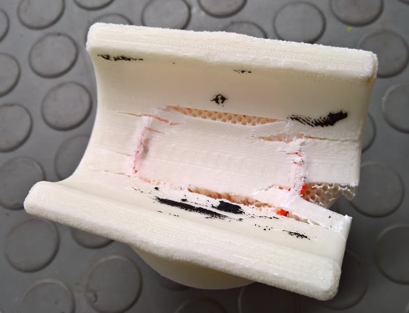
Partial failure occurred at ~ 1.1 tonnes, followed by full failure at ~ 1.4 tonnes :-
Here is the component after final failure :-
At this point, it still would have provided protection for the radar bridge against the metal table support :-
but thankfully it won't see anything like this load in actual use !
The completed supports:-
|  Kevin Millican

.jpg)


.jpg)